

, a boost converter topology is commonly used. It is advantageous for minimizing the harmonics of)
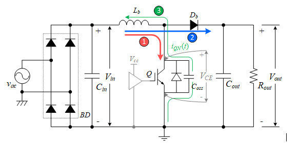
For power factor correction (PFC), a boost converter topology is commonly used. It is advantageous for minimizing the harmonics of the input current, since it provides the input current continuously. Meanwhile, IGBT is the best choice for high-power PFC applications such as air-conditioners, heating, ventilation, and air conditioning (HVAC), and heat pumps.
Theoretically, in continuous conduction mode (CCM), a reverse-conducting current through the IGBT never occurs. However, under a light load or transient conditions, a reverse current flows through it, due to the resonance between the boost inductor, Lboost and the output capacitance, Coss of the IGBT.


This resonance current, iQN(t) is given as:
![]()
The voltage across the IGBT (VCE) during resonance can be derived as:
When the input voltage, Vin, is lower than half of the output voltage (Vin <Vout/2), the switch voltage VCE becomes negative. This negative voltage appears across the IGBT, if there is no reverse conducting path available in parallel to the IGBT, Q, of the boost PFC in Figure 1. If you don’t consider the damping factor, the magnitude of the reverse voltage near the zero crossing point can theoretically reach up to the same amount as the output voltage Vout. This is very risky in terms of the system’s long-term reliability, because it does not guarantee a reverse voltage is applied to the IGBT.

Comparing different IGBT solutions for PFC applications
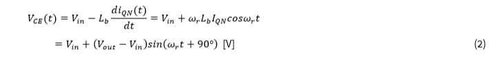
This phenomenon has been demonstrated experimentally by comparing the operating waveforms of the TRENCHSTOP™ 5 WR6 IGBT (IKWH30N65WR6) and the TRENCHSTOP™ IGBT3 (IGW30N60H3) in a CCM-boost PFC circuit. The IKWH30N65WR6 contains a reverse-conducting diode, monolithically integrated in the IGBT die, while the latter IGBT doesn’t contain a reverse-conducting diode. Figure 2 shows that with the IKWH30N65WR6, the reverse voltage is clamped to near zero. In the case of the IGW30N60H3, the reverse voltage reaches up to – 241V. Therefore, the reverse conducting diode is essential to ensure the system reliability, even in the PFC’s CCM operation.
Yet, in this case, we don’t need a high-performance, co-packed diode for the small amount of soft recovery reverse current. In Figure 2, you can see the reverse current of the IGBT has a peak value of only about 200 mA and a duration of few µs.
Reverse-conducting (RC) IGBTs with monolithically integrated reverse-conducting diodes are not suitable for applications where hard commutation occurs. However, RC IGBTs can be very beneficial for some hard-switching applications such as PFC, where the reverse-conducting diode of the IGBT doesn’t need to have good reverse-conducting performance. In such applications, they present a much more economical option when high-performance diodes would be superfluous.
TRENCHSTOP 5 WR6 IGBT for boost PFC and welding applications
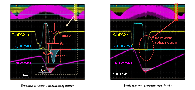
Infineon’s latest RC IGBT, as shown in Figure 3, is based on TRENCHSTOP 5 WR6 IGBT technology, in which the N+ region is partially implanted into the P-collector layer, forming an intrinsic P-N diode. This allows a reverse current to flow without the need for an additional co-pack diode.
This TRENCHSTOP 5 WR6 IGBT is well-suited for boost PFC and welding applications. Optimizing the thickness of the drift region and the diode rating to the target application ensures the best-in-class VCE(sat) of 1.4 V at rated current, while maintaining the rated voltage of 650 V. In addition, thanks to its extremely reduced minority-carrier lifetime, a tail current does not appear, which allows the TRENCHSTOPTM 5 WR6 IGBT to achieve a higher switching frequency of 60 kHz or even higher.
When choosing TRENCHSTOP 5 WR6 IGBT for PFC applications in which hard commutation doesn’t occur, there is no need to worry about the performance of the intrinsic diodes. With this technology, it is possible to create economical and reliable systems for your next design.
Courtesy: Infineon