

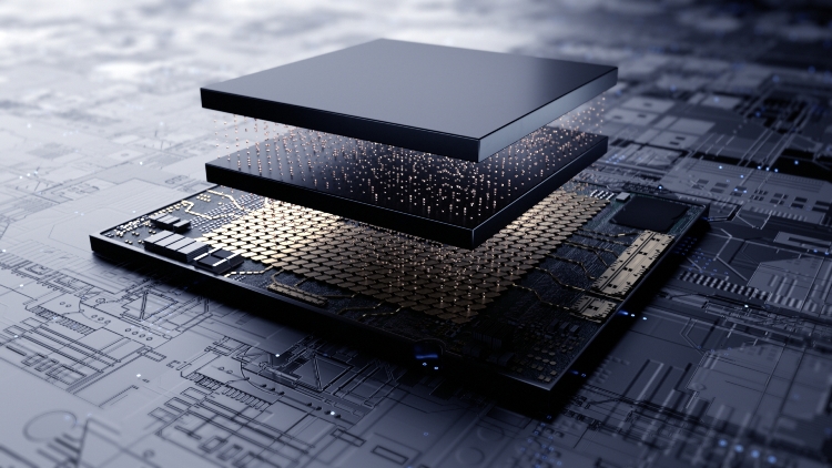
As we try to increase the efficiency and performance of chips, it is getting more and more complex. But the new architecture of 3D ICs is somehow making things handy to some extent. 3D ICs not only provide improved interconnect performance, increased transistor packing density but also reduce chip area and power dissipation. While talking of 3D ICs, it is mandatory to have a few viewpoints of one of the industry’s major players. Cadence Design Systems is one such player in the industry.
Our ELE Times Sub Editor & correspondent Sheeba Chauhan took this opportunity to interact with Vinay Patwardhan, Product Marketing Group Director, Digital and Signoff Group, Cadence Design Systems, Inc. for an exclusive conversation on advancing chip design with the new architecture. Excerpt:


ELE Times: 3D ICs are ideal for applications that benefit from more transistors in a given footprint say Mobile SOCs. Please tell us about some more practical applications of 3D ICs.
Vinay Patwardhan: 3D packaging where multiple packages are stacked has been around for some time. What has changed recently is advancements in foundry technology with which ICs or multiple chiplets can be integrated in the same package by either mounting them or connecting to one other through the use of a silicon interposer or similar technology. With this shift, the number of transistors in the same package has increased by many times, and 3D-IC applications have broadened quite a lot. Mobile SoCs is one advanced packaging area where this is prevalent. Another major application area is high-performance computing/data center types of designs where large data-centric SoCs involve massive amounts of data movement. With growing functionality needed and die size limitations for some large SoCs, 3D-ICs can reduce power area and even improve performance, which is a very attractive value proposition. Other key applications that come to mind that can be mounted in a 3D configuration are image sensors that are used in cameras and photonic sensors as well as some medical and IoT devices, which require a small form factor.
ELE Times: With the coming innovations in the chip industry, everything is taking a miniaturized form. What do you think the role of Moore’s law in the miniaturization of devices today?
Vinay Patwardhan: Moore’s Law has been the guiding principle for IC design for many years. It still plays a very important role in defining roadmaps and future designs. However, now that we are at 3nm, technology node scaling is reaching physical transistor size limitations. To address current design trends, 3D-ICs are needed to keep Moore’s Law scaling.
ELE Times: Thinking about 3D ICs only in terms of stacking 2D chips on top of each other is insufficient. Please get us familiar with three-way optimization for power, performance and area (PPA) that still applies.
Vinay Patwardhan: These days, some of the GPUs, AI chips and CPUs are approaching reticle limits with large die sizes. Physical IC design with advanced PPA requirements is getting harder to achieve. When you stack ICs on top of one other, long wires that normally go long distances across a chip now can connect to the chip stacked above. Thus, by making use of the Z dimension, there can be shorter a wirelength for the switching signals. Shorter wirelength leads to reduced switching power, and hence, power savings. Shorter wires or critical paths can also lead to improved performance, and because the two chips stacked on one another need to have large sizes, there is area savings as well.
ELE Times: Do you think the end of Moore’s Law will create major challenge in the making of microchip for future advanced devices?
Vinay Patwardhan: As mentioned earlier, we are reaching reticle limits, but we are also at a very innovative time in our industry. The industry will overcome challenges with device-level design as well as creative solutions like 3D chip-stacking.
ELE Times: 3D ICs have great potential for types of electronic products. The reduced footprint and improved power efficiency are valuable for mobile devices, Internet-of-Things (IoT) and other applications. What is your take on the same? Do you like to add something to the potential benefits of the 3D ICs?
Vinay Patwardhan: A reduced footprint is a major advantage of 3D-IC design. If same functionality can be achieved with a smaller form factor, it becomes a creative, cost-effective solution for many applications. Photo sensors, medical devices, smart glasses, automotive designs—these are all areas that require smaller form factors and can benefit from 3D-ICs. Also, since the individual die sizes are smaller, the manufacturing yields will be better, which saves costs as well.
ELE Times: Despite all the opportunities and benefits, 3D ICs throw some major challenges in design flows. What are these challenges according to your experience?
Vinay Patwardhan: Planning, designing, analyzing, and manufacturing multi-chiplet 3D-ICs comes with its own set of challenges. With existing tools and methodologies, it is possible to do a “die-by-die” design and connect pieces on an interposer or RDL layer. This is a bottom-up approach used for today’s multi-chiplet designs where different chiplets and packages are designed by individual project teams and off-the-shelf IP is selected. After the assembly, some top-level routing is done with a combination of routing solutions that can make specific angled routing shapes. However, there are a few limitations with this approach:
- Not all components are designed to be optimal for interfacing with each other or for particular application types. This can cause a costly overdesign with individual dies, or chiplets may also bring down system performance as a whole.
- There must be an effective way to do top-level aggregation and abstraction to build the whole system with bump planning and interconnect optimization, taking into account the placement of chiplets on the package substrate. Many times, this step causes too many iterations due to incorrect abstraction.
- A collection of predesigned chiplets added to the package creates an aggregated system. Although each individual chiplet has passed signoff checks—such as static timing analysis (STA), power, and EM-IR—chiplets connected together in a system require additional verification. The definition of design closure now involves system-level closure with additional verification checks such as thermal and mechanical stress checks, which are required for long-term effects like warpage. Also, electromagnetic interference (EMI) and signal and power integrity (SI/PI) analysis are needed for chiplets placed next to each other on RDLs or silicon interposer layers.
ELE Times: The power density is higher for a given footprint than for traditional 2D chips. What are the power and thermal challenges you face while working on 3D IC projects?
Vinay Patwardhan: Power and heat dissipation are certainly the most important aspects of 3D IC projects. When ICs are stacked together, it is important to look at the power density hotspots and make sure high-activity switching logic from both ICs is not placed on top of one other. If that happens, the overall system temperature will go up due to a chimney effect caused by interconnected metal stacks, which will provide the path for heat dissipation. Therefore, early power and thermal analysis of the whole 3D stack during the design phase are of paramount importance.
ELE Times: How do you see the future innovations in the ICs and what interesting projects can come up your way with the coming of the newest innovations?
Vinay Patwardhan: To address the challenges mentioned above and the innovation needed to address them effectively, Cadence recently announced a breakthrough innovation platform for 3D-IC design, the Cadence Integrity 3D-IC platform. This high-capacity analysis platform is built on the infrastructure of Cadence’s leading Innovus™ Implementation System and helps system-level designers plan, implement and analyze any type of stacked die 3D-IC system with a variety of packaging styles (2.5D or 3D). It is the industry’s first integrated, comprehensive system and SoC-level solution that enables system analysis technology and co-design with analog and package implementation environments. Integrity 3D-IC provides an integrated flow manager for the setup of system-level analysis capabilities for thermal analysis, power analysis, inter-die static timing analysis, and physical verification early on to achieve efficient closure not just at the individual die-level but on the system as a whole.
ELE Times: Tell us about some biggest megatrends that Cadence is going to pursue in 2022.
Vinay Patwardhan: One of the biggest megatrends in 3D-IC design to watch in 2022 is advanced packaging and stacked multi-chiplet design. Due to the advantages mentioned previously and the advancements at major foundries in advanced packaging technology offerings, the disaggregation of SoCs and multi-chiplet design is certainly going to be one of the megatrends that offer a creative solution to push technology forward for large hyper-scale data center companies as well as markets like mobile, 5G, AI and automotive. New demands for data handling and faster connectivity are accelerating the need for cutting-edge methodologies. Cadence, being a technology leader, is consistently at the forefront of innovation with its computational software solutions, which enable customers to solve the world’s toughest design challenges.
Sheeba Chauhan |Sub Editor | ELE Times