")
Automated inline handler systems for in-circuit testers rely on numerous sensors
fitted around the system to detect and control mechanical operations.
The programmable logic controller (PLC) runs a set of complex algorithms that supervise all handler operations and maintain control of safeguards. This ensures consistent and safe operation of the system. To prevent any external interruption to its operation, the PLC does not allow any user intervention to its process once it starts the automated operation. As such, most of the automated inline systems have a closed-loop design that does not allow user customization of the handler operation.


However, it is possible to split the PLC’s algorithms into sections without degrading the robustness of the safeguards. In doing so, it opens little windows of opportunities into the PLC’s control of the handler and allows customization of the handler operations to suit user requirements.
My previous post shared some of the test steps in the i7090 plug-in for Pathwave Test Executive for Manufacturing (PTEM) application which allow you to configure the i7090 system handler profile and monitor the error codes during runtime. Figure 1 below recounts the flowchart that I discussed before.
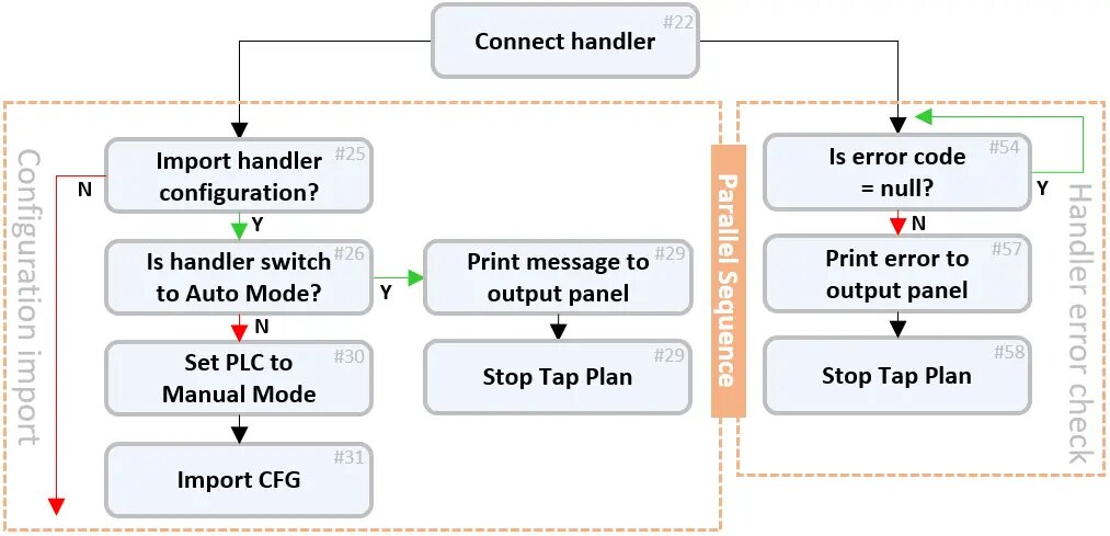
From the flowchart in Figure 1, configuration import is an optional process as user can also set up the handler profile directly on the i7090 system handler application itself. You may choose to omit the configuration import and go directly to the next stage in the process.
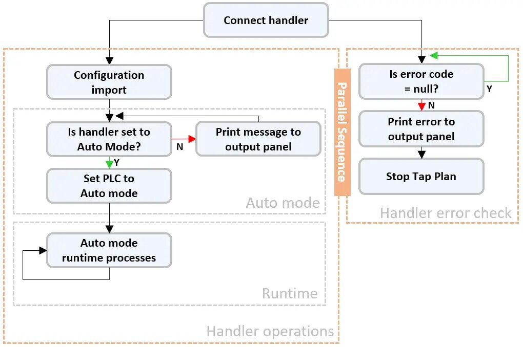
The next stage of the handler operation includes setting the handler into auto mode operation followed by the runtime processes. By combining the configuration import sequence into a single bubble and adding the auto mode and runtime processes, the updated flowchart is as shown in Figure 2. Since configuration import is optional, the flow can go directly into the Auto mode process after the handler control is connected to PTEM.
Switching the handler into auto mode lets the PLC take over command of the handler operations and execute the handler initialization algorithm. During the initialization process, you can continue to monitor the handler error codes and terminate the operation if required. However, you cannot alter the initialization steps that the PLC dictates. In this post, I will share details of the events during the initialization process when you set the handler to auto mode. We will leave the runtime processes to the next post.
Getting into the auto mode operation is a two-step process.
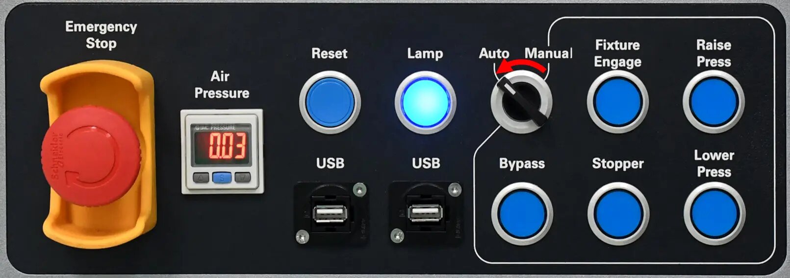
First, switch the handler into auto operation by turning the selector switch on the machine panel from Manual to Auto as shown in Figure 3.
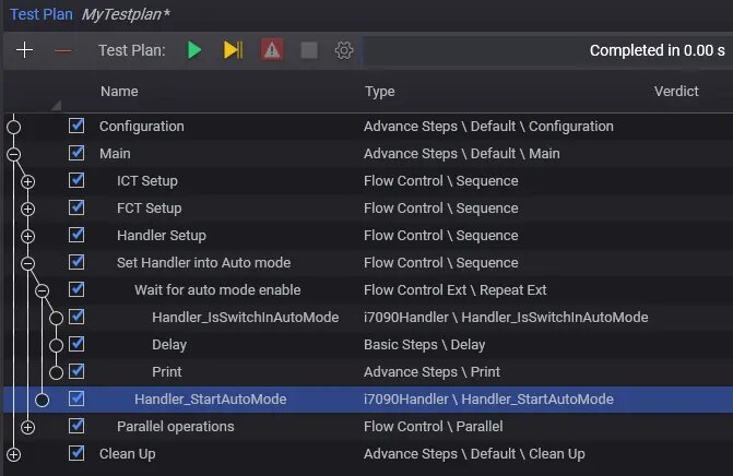
The next step is to start the auto mode operation in the PLC. In the PTEM testplan shown in Figure 4, I created a repeat loop to monitor the selector switch using the Handler_IsSwitchInAutoMode test step and waited for it to enter the auto position. Within the loop, I included a print step to display a text message and prompt the operator to make the switch. Once the selector switch is in auto, the repeat loop exits and calls the Handler_StartAutoMode test step to start auto mode operation at the PLC.
In auto mode operation, the handler starts with the initialization of the hardware before going into the board transfer stage to bring in the device under test (DUT). For initialization to happen, the handler must not be in any error state, and the fixture must be correctly locked down, with all doors closed. No foreign items, including any DUT, should be in the test bay area or on the fixture. Make sure to remove any tools or equipment from the test bay before triggering auto mode operation. Monitor the initialization sequences as the testplan executes, to confirm that the handler receives the correct commands before leaving it to run on its own.
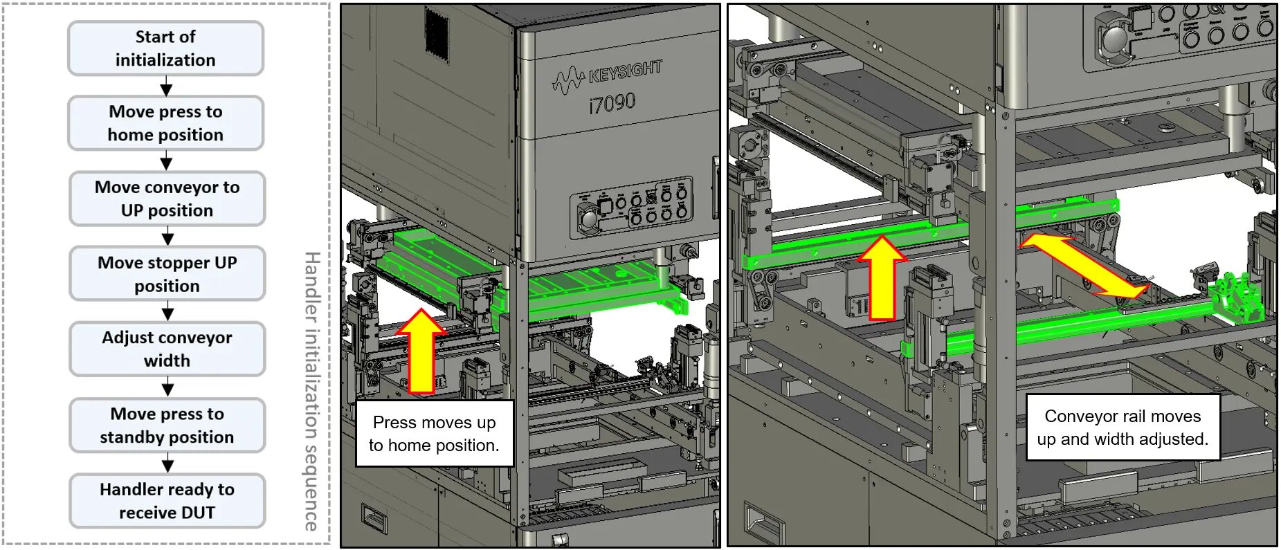
Initialization starts with the press, conveyor, and stopper returned to their home positions. The first action to expect after going into auto mode is that the press should start to move upwards, followed by the conveyor rail and stopper. During the process, the PLC monitors all the position sensors in the handler and reports errors if any one of them fails to respond correctly. The completion of these movements is confirmation that the mechanical hardware is functioning well.
Next, the handler configures the width of the conveyor to the targeted setting in the system handler application. You will notice the handler moves the rear conveyor outwards to its home position, and then inwards until it reaches the targeted width. If adjustment is successful, the adjusted width matches that of the DUT, else it is an indication that you may have set the parameters wrong, or the adjustment motors are defective.
The final phase of the initialization process is getting the press ready at the standby height position. From its home position at the top, the press moves downwards and halts at the standby height position. Standby height is the position of the press where it is slightly above the DUT. This gives sufficient clearance for the DUT to pass under it and move to the stopper position. Moving the press downwards from the standby height is more efficient than having the press to travel from the home position at the top. This reduces the time it takes to engage the DUT into the fixture. Once the press reaches standby height, the handler is now ready to receive DUT. Once the upstream conveyor presents a DUT to the handler, the transfer will begin automatically.
The testplan is now in the parallel operation process where it is constantly monitoring for errors and waiting for the DUT to get into position. Once a DUT is in position, the testplan continues into the runtime operation, which we will discuss in the next post.
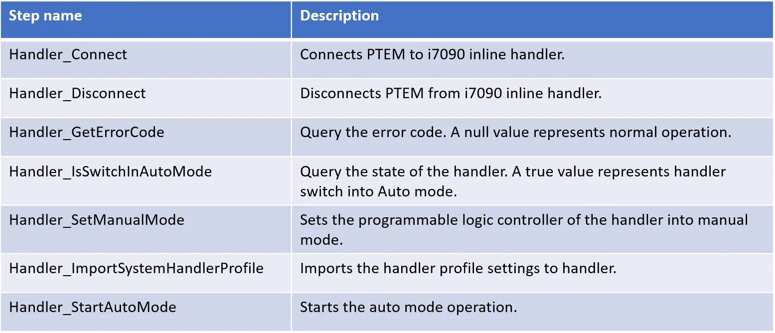
Table 1 tabulates all the test steps that I have discussed so far in all my posts on automation control of the i7090 system. You can also check out my previous post on Keysight i7090 with PTEM where I shared how the error monitoring sequences can be created easily with PTEM. Meanwhile, if you have questions or comments regarding what you have just read, feel free to send me a message.