


Courtesy : Infineon
You may already be familiar with the CAPSENSE technology present in our PSoC family of devices. This technology enables high performance touch detection using capacitive sensing. However, did you know that our PSoC 4700S devices include an additional sensing mode in our CAPSENSE hardware? Not only does the device support our capacitive sensing, but it also enables inductive sensing.


In this blog post, we will explore the inductive sensing technology and some of its differentiating capabilities that enhance user interfaces beyond the conventional.
First, let us take a look at the fundamentals of inductive sensing.
Inductive Sensing
Inductive sensing utilizes electromagnetic coupling between an inductor coil and a target metal to generate signal. The CAPSENSE hardware in the PSoC 4700S drives an AC signal into a tank circuit to elicit an electromagnetic field emanating from the inductor. A nearby metal target interferes with the electromagnetic field, changing the resonant frequency of the tank circuit. The PSoC 4700S device detects this change and converts it into a digital signal.
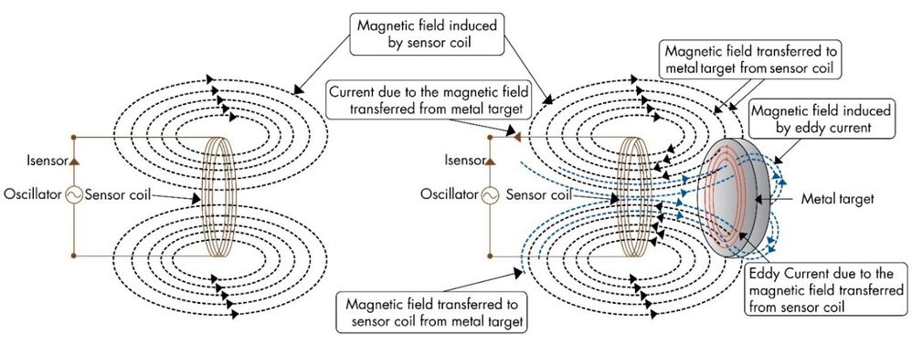
The signal generated is proportional to the proximity of the target metal to the coil, and is largely unaffected by the presence of a hand. This allows inductive sensing to perform exceptionally well in systems with metal surfaces, where capacitive sensing performance may degrade.
Metal-over-touch System
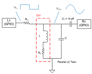
An inductive sensor for the PSoC 4700S is created with tank circuit components including the PCB trace coil, parallel capacitor, decoupling capacitor, and a series resistor. Two pins are also used; a Tx and an Rx pin. You can select your component values by following the instructions in our Inductive Sensing Design Guide application note.
The inductor in the tank circuit may be created from a multi-layer PCB trace routed in a 2-D coil-like shape. As a result, it is simple to place flat metal materials as an overlay on inductive sensors.
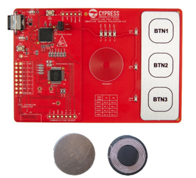
We can take a look at the CY8CKIT-148 for an example of a metal-over-touch inductive sensor system:
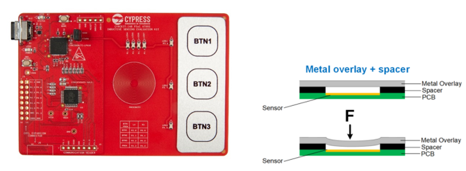
The construction of a metal overlay is simple, involving only the spacer adhesive and the actual metal itself. The spacer is needed to create some range for deflection of the metal overlay on a touch. This simple construction combined with the inductive sensing technology enables some seriously sleek metal user interfaces.
Force Sensing
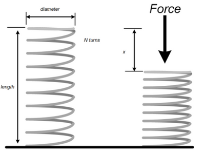
The metal-over-touch system described above implements a form of force sensing, wherein a measurable amount of force produces a change in signal. A more robust version of force sensing can be implemented with a metal spring.
There are two key principles that we can utilize to determine force from a spring compression.
- Hooke’sLaw:
![]()
- Wheeler’sEquation:
![]()
To utilize Hooke’s law, we must have a known spring factor (K). The inductive sensing system determines the displacement, which we can then use to calculate the force applied to the system.
To utilize Wheeler’s equation, the spiral coil is connected as the inductor. In this case, we need to know the dimensions of the coil shown in the above equation. As the length decreases, the other parameters remain constant, allowing us to derive a curve of inductance proportional to the displacement of the spring.
In conjunction, these two equations can provide a complete picture of force derived from a change in inductance.
Water Resistant Touch
If you want a robust and sleek touch interface to work well under wet conditions, inductive sensing is right for you. The inductor coils are not impacted by water or other non-conductive materials.
Metal overlays can be carefully selected to provide an appropriate amount of deflection under the pressures at depth for your device. Alternatively, a gap can be created between the overlay metal and the sensors, allowing for water to equalize pressure at all depths.
Keep in mind that any exposed components other than the sensors themselves will still need to be properly contained and protected from water.
Object Detection
Different materials impact the electromagnetic field in different ways, generating a signal that can be used to determine the type of material. Non-magnetic metals tend to increase the system’s frequency while decreasing the amplitude. Magnetic materials and other inductive coils tend to increase amplitude while decreasing the system’s frequency.
We tested 6 different materials to see what their frequency response was when brought in range of a 15mm inductor coil:
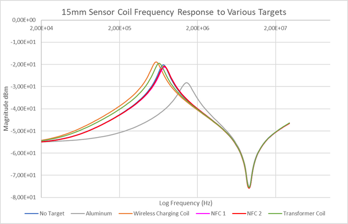
Clearly the Aluminum metal showed the expected decrease in amplitude and increase in frequency, while smaller coils (NFC tags Pink and Red) had minimal impact. The larger inductor coils also share the expected result of increasing the amplitude and decreasing the system’s resonant frequency.
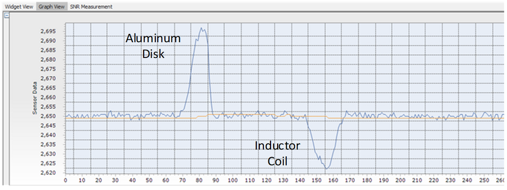
We can leverage these results to develop a quick application that detects the presence of a metal or a larger coil object. The CY8CKIT-148 has the necessary inductive sensing hardware. With this kit, we can use the code example CE223813 Inductive Proximity Sensing without any modifications. I’ve selected an aluminum disk and a large inductor coil as the objects to detect.
The raw counts data shows a clear inversion of signal when detecting the inductor coil:
Conclusion
Inductive sensing can provide an expanded set of capabilities to your touch HMI, including water tolerance, force touch, and object detection.